
Cisco Engage Boise 2020: Get Your Programability On

Note: I wrote this the evening of the event. Just getting around to publishing it now.

Another day has gone and another Cisco Engage Boise is behind us. This year at Cisco Engage Boise 2020, there was a very clear theme that I took away: network engineers need to be adding programability to their skill sets.

Cisco Engage

Note that I used the term programability and not automation. I think Cisco did a fantastic job making this distinction because the term automation gets thrown around a lot in engineering circles, often mistakenly conflated with scripting, or perhaps even with programability.

So what is programability and how is it different than automation? In my mind and in the context of network engineering, programability is an approach to network engineering that utilizes APIs and other tools within a software development framework to accomplish network engineering tasks. Automation, on the other hand, utilizes programability, but uses it to repeat tasks on regular intervals or based on events, both without the need of human interaction.

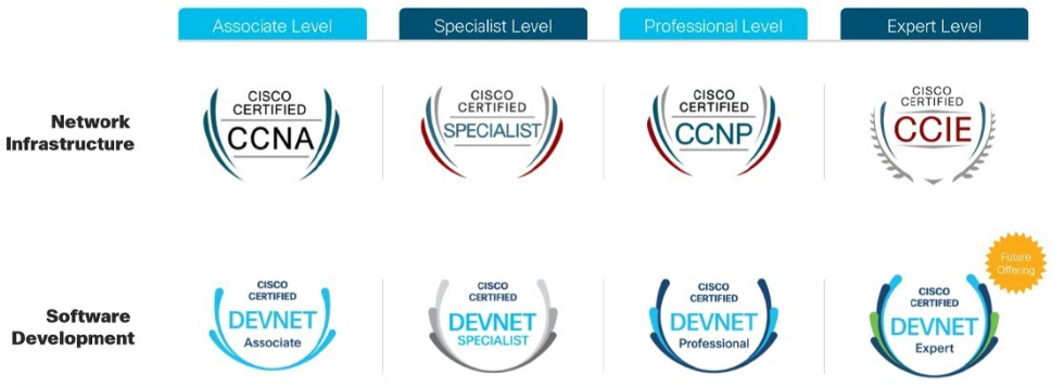
Cisco made it abundantly clear that future of networking involves incorporating programability into your skill sets, and they’re emphasizing this so much that they’re incorporating programability into the new certifications (click here or here for a great explanation). The engineering tracks will have 80% engineering and 20% programability, whereas the new developer-focused certifications will have 80% development, 20% engineering.

Cisco certifications, showing an engineering track and developer track of certifications.

Cisco is also pushing this paradigm shift by offering a ton of resources on it’s learning platform DevNet, which has a lot of cool resources, and was also a topic that received a lot of airplay today.

Personally, I’ve long held the belief that programability is the future for network and system engineers alike, but to be completely honest, I’ve often been guilty of using the term automation to describe something that I didn’t have great word for. It’s great to see Cisco finally start pushing this, but I must say other vendors having been pushing programability and education on this topic for awhile now; why this is more relevant now is because the big player in this industry, Cisco, is pushing it now, so hopefully we’ll get better programability offerings such as APIs, structured data models, etc.

Sessions

Of course, it goes without saying that Cisco Engage Boise 2020 also had sessions, but to be honest, I don’t think there’s much to note that hasn’t already been mentioned on Reddit or discussed by Packet Pushers. There were a few different sessions to select from, but no tracks, so I went to sessions I thought were interesting for my interests right now (largely operational logistics and preventative analytics).

For conferences and sessions, I must say I have a bit of fatigue for security topics right now, especially on the networking front, so I avoided those. I don’t think anyone is really presenting anything new with security, and most of the fashionable topics are largely relevant to the higher tier of the NIST or CIS security frameworks. Most issues are addressed in the lower tiers, and it’s in those tiers where I’m interested.

That said, for the sessions I attended, I have just a few notes worth writing about:

  • Zero Trust –  Cisco’s philosophy to zero trust is like others: assume the traffic malicious until proven otherwise. Cisco basically believes there are three components that need to be addressed in order move towards a zero trust framework, so Cisco has a off-the-shelf framework for you to purchase and implement. The framework:
    • Users need to be interrogated and challenged for access. Cisco product: Duo.
    • Workloads need to be monitored and inspected for malicious activity. Cisco product: Tetration.
    • Workplaces need to be secured and addressed. Cisco products: DNA, SD-Access and/or ISE.
  • Hyperflex – This is Cisco’s hyperconverged infrastructure, and of note Cisco is going to be deploying Cisco Hyperflex Application Flatform (HXAP), which is a hypervisor to compete with the likes of VMware and will include it’s own Kubernetes implementation. Initially HXAP will be focused on containers, but eventually will grow to allow VMs and so forth. They noted that you’ll be able to avoid the ‘VMware tax’, but I’m certain that will just be replaced with the ‘Cisco tax’.
  • DNA – DNA was definitely featured in a few of the sessions I attended, but I don’t care to go into the details of it. DNA basically is a platform to monitor and manage anything and everything about your Cisco network gear (well, only stuff that does 16.9, and basically on the hardware side is limited to 3850s and 9000 series gear). What really stood out to me about watching DNA in action for the first time was why Juniper made it’s Mist acquisition, because Juniper doesn’t really have a complete product to compete with DNA (yet, but they are making great strides). However, having features and having capabilities is one thing, but execution and proof of execution is a whole other thing — not to mention the price tag for the full vertical integration of everything to integrate with DNA.

Final Thoughts and An Evolving Mindset

When I signed up for Cisco Engage, I fully expected product evangelism — and I was not disappointed. I have a bit of an allergy to sales for some reason, but I’ve been challenging myself about this topic recently, and as a result, I found today’s conference quite useful.

That said, what I’m finally coming around to is the notion that I am a network engineer first (although I use engineer quite loosely here), and a user of products second. At a fundamentally high level, I am trying to solve networking problems for the organization I’m a part of, helping us accomplish our goals the best I think we can. It mostly doesn’t matter what products we deploy and use, as long as we can accomplish what the business needs us to.

I realize that’s not too much of a profound thought, but at times I feel like there’s a religious battle that continually takes place between vendors x, y, and z, aa, bb, etc. The reality is that, to paraphrase a podcast I was recently listening to, the technology landscape is much more diverse than just one or two vendors; there is plenty to learn from out there, and I think limiting yourself to one or even two vendors might force you into a paradigm/framework bubble that may not even be the best solution for your problems, maybe even stifling your ability to think more critically and out-of-the-box.

As a result, I’m trying to stay open to more ideas in networking, trying to not see every problem as a nail.

Connecting to Multiple Devices with Netmiko Using Python Threads and Queues

tl;dr – Click here to go straight to the Python example.

The journey to automation and scripting is fraught with mental obstacles, and one concept I continued to not really comprehend in Python was the concept of threading, multiprocessing, and queuing.

Python Logo

Up until recently, I felt like I basically had my dunce cap on (relatively speaking, of course) and was restricted to sequential loops and connections — in other words, I was stuck in “for i in x” loop land and could only connect to one device at a time. In order to speed up my scripts and connect to multiple devices at once (using Netmiko, for example), the path to that is through queues, and threading/multiprocessing.

Ultimately I landed on threading instead of multiprocessing because when you’re connecting to devices/APIs over the network, you’re typically waiting for a remote host to process the request, and thus your CPU is sitting there ‘idle’ waiting. To quote a great blog post that breaks down threading versus multiprocessing:

“[t]hreading is game-changing because many scripts related to network/data I/O spend the majority of their time waiting for data from a remote source. Because downloads might not be linked (i.e., scraping separate websites), the processor can download from different data sources in parallel and combine the result at the end.” (source)

While the above link has some great examples, for some reason I still didn’t quite grasp the concept of threads and queues, even after trying the example of other approaches. Why? Well, sometimes we need different perspectives to a problem because we all learn differently, thus my hope here is to provide a different perspective to threading and connecting to multiple devices with Python.

Netmiko Using Threaded Queue

I don’t want to waste to much time, so let’s just cut to the chase and get to the script:I’m going to try a different approach here, so here’s an overly verbose perspective on how the script runs. It’s a step-by-step breakdown of how it processes. That said, as much as a I tried to describe the process in a linear manner, it’s not going to be perfect.

  1. Load and stage the modules and terminal messages relating to hitting ctrl+c. (lines 6-20)
  2. Load the global variables (lines 23-38)
    1. Prompt the user to securely enter a password (var: password) (line 23)
    2. Read a list of IP addresses from text file (vars: ip_addrs_file and ip_addrs) (lines 26-27)
    3. Set up the number of threads to spin up (var: num_threads) (line 30)
    4. Set up the global queue that we’ll use to set up a list of ip addresses to be processed later (var: enclosure_queue) (line 32)
    5. Set up an object that we’ll use to lock up the screen to print the contents of a thread so as to avoid having threads print over each other later (var: print_lock) (line 34)
    6. Set up the command you’ll want to run. This is a simple one command script for the purpose of the demo. (var: command) (line 38)
  3. The two functions deviceconnector() and and main() get loaded and staged. (lines 41-107)
  4. The main() function is called and begins the execution of the main components of the script (line 112)
    1. Loop through a number list (num_threads), and for each number in that list (i): (line 92)
      1. Load a thread that runs an instance of deviceconnector() sending to the function the thread number (i) and the global queue (enclosure_queue) (line 95)
        1. deviceconnector() accepts the variables i as i, and enclosure_queue as q (line 41)
        2. deviceconnector() starts an unending while loop that: (line 45)
          1. Attempts to acquire an IP address from the global queue (line 50)
            1. If there is no IP address in the queue, the while loop will be blocked and wait until there is an ip address in the queue
          2. Sets up dictionary for Netmiko (lines 54-59)
          3. Netmiko attempts to connect to the device (lines 52-53)
            1. If there is a time out, lock the process and print a time-out message, marking the queue item as processed and restarting the while loop (lines 55-58)
            2. If there is an authentication error, print an authentication error and exit the whole script (lines 70-73)
          4. Send command to the device, lock the process and print the output (lines 76-80)
          5. Disconnect from the device, mark the queue item as complete, and loop back (lines 83-86)
      2. Set the thread to run as a daemon/in the background (line 97)
      3. Start the thread (line 99)
    2. Loop through a list of IP addresses (ip_addrs), and for each IP address (ip_addr) (lines 102-103)
      1. Add the IP address (ip_addr) to the global queue  as an individual queue item to be processed (line 103)
    3. Wait for all queue items to be processed before exiting the queue and script (line 106)
    4. Print a statement to the console indicating the script is complete (line 107)

Use this as you wish, and hope it’s helpful.

Here’s the Github version.

Credit and Additional Info

This was inspired by a few different blog posts, so here’s some additional info to follow:

  • Multiprocessing Vs. Threading In Python: What You Need To Know.
    A great breakdown of threading versus multiprocessing, and influential for some of the work I’m doing.
  • How to Make Python Wait
    This one actually reignited my interest in figuring out how to use threading. It’s a good explanation of the different approaches to make a script wait in Python.
  • Queue – A thread-safe FIFO implementation
    Although written in Python 2, this post helped me put everything together so I could understand what the heck is going on. Some of the code I used here, but refactored for Python 3. Below is a crude diagram I did to help me figure out what was going on with this post, and the circles with arrows indicate loops, with the ‘f’ in the middle meaning ‘for’ loops and ‘w’ meaning ‘while’ loops.

Diagram that attempts to show how the thread and queue process works. Too complicated to explain in an alt tag, so look at code.

Juniper Interface-Range: A Use Case

It’s holiday break! That means I have more discretionary time for topics such as… Juniper interface-ranges! Yay! Right?

Unenthusiastic Fry from Futurama

Ok, not the most exciting topic in the world, but hear me out — I think there’s a pretty good use case for using Juniper interfaces-ranges, which is a Junos feature that I think really stands out from other NOS’ that I’ve had exposure to. What is the use case? Simple: campus switch port configurations.

What is a Juniper interface range?

Let’s start by explaining what it is and is not, because if you’re coming from other vendors, the concept may be foreign and/or you may conflate it with features from others.

An interface-range is a logical construct in a Juniper configuration that aggregates multiple port configurations and places them into one configuration. Here is an example:

interfaces {
    interface-range workstations201 {
        member ge-0/0/0;
        member ge-0/0/1;
        unit 0 {
            family ethernet-switching {
                interface-mode access;
                vlan {
                    members 201;
                }
            }
        }
    }
    interface ge-0/0/0 {
        description "Workstation 1";
    }
    interface ge-0/0/1 {
        description "Workstation 2";
    }
}

Here I have two interfaces that are members of the interface-range ‘workstations201’; they both are access ports and both belong in VLAN 201. Here’s the configuration if I were to separate out the interfaces into separate configurations:

interfaces {
    interface ge-0/0/0
       description "Workstation 1"; 
       unit 0 {
            family ethernet-switching {
                interface-mode access;
                vlan {
                    members 201;
                }
            }
        }
    }
    interface ge-0/0/1
        description "Workstation 2";
        unit 0 {
            family ethernet-switching {
                interface-mode access;
                vlan {
                    members 201;
                }
            }
        }
    }
}

As you can see above,  interface configurations are often repeated multiple times if you configure them one-by-one, but interface-ranges simplify port configurations and reduce the number of lines of these repeated configurations (in a 48-port switch with each port the same, theoretically using an interface-range could remove up-to 384 lines). If you need to change a port to a different VLAN or different configuration, simply delete the interface’s membership from one interface-range and place it in another.

What interface-ranges are not: CLI commands for making mass interface changes. For that, Juniper has the wildcard range command. For more info on that here.

Configurations Beyond the Individual Interface

So reducing the number of lines of configuration is great, but so what? If you come from the world of other vendors, you’re already used to the idea of keeping port configurations and their protocols all in the interface’s configuration, so configuring edge ports this way isn’t going to offer you much.

In the Junos world though, interface’s don’t hold all the configurations for the ports. For example, if you want to configure a voice/auxillary VLAN, that configuration on Junos (well, in post ELS change*) is in the switch-options stanza of the configuration. Sure you could configure switch-options like this and have all access ports configured for VoIP like this:

switch-options {
    voip {
        interface access-ports {
            vlan PHONES;
            forwarding-class expedited-forwarding;
        }
    }
}

But what if you have devices that will utilize the voice/auxiliary VLAN, but you want them specifically in a separate VLAN than your voice/auxiliary VLAN? You would have to configure each port specifically for that protocol like this:

switch-options {
    voip {
        interface ge-0/0/0 {
            vlan PHONES;
            forwarding-class expedited-forwarding;
        }
        interface ge-0/0/1 {
            vlan PHONES;
            forwarding-class expedited-forwarding;
        }
    }
}

If you needed to make a change for an interface, and you’re doing this via CLI, managing these changes could get daunting.

Let take another place where configurations aren’t located in the same location: spanning-tree. It’s not enough in Junos to just turn on spanning-tree on all ports; you need to specify which ports are edge (to block BPDUs) and which ones are a downstream switch (ignore BPDUs). Often I have seen Junos configurations for campus gear look like this:

protocols {
    rstp {
        interface all;
        bpdu-block-on-edge;
    }
}

But from my experience, all that does is turn on RSTP, and ‘bpdu-block-on-edge’ does nothing because no ports are designated as ‘edge’. In order to accomplish the above, you need to designate edge ports and ports for downstream switches (no-root-port):

protocols {
    rstp {
        bpdu-block-on-edge;
        interface ge-0/0/0 {
            edge;
        }
        interface ge-0/0/1 {
            no-root-port;
        }
    }
}

Great, so now you’re having to manage port configurations in three stanzas, and you’re adding a hundreds of lines of configurations to each switch configuration. WTH, Juniper?

If only there was a way to simplify this…

Where Interface-Range Shines

Interface-range does simplify all of this and reduce the lines configuration! Instead of blabbing on and on about this, let me just show you exactly how this is simplified:

protocols {
    rstp {
        interface all;
        interface workstations201 {
            edge;
        }
        bpdu-block-on-edge;
    }
}
switch-options {
    voip {
        interface workstations201 {
            vlan PHONES;
            forwarding-class expedited-forwarding;
        }
    }
}

Using interface-range, we can treat the interface-range as an interface object and apply configurations to it just like you would individual interfaces. For ports needing voice/aux VLANs, we can configure only the ports needing it; for spanning-tree, we can designate edge and no-root-port more simply.

Another great example: what if you needed to quickly power cycle all IP speakers? Sure, you could set the following in CLI:

wildcard range set poe interface ge-0/0/[0-2,5,10,18] disable
commit

But what if you’re working in a virtual-chassis, and your wildcard range command won’t work to get all the ports in one line? Using interface-range, you can get them all in one line like this:

set poe interface ip_speakers disable
commit

Then BAM! You’ve turned off PoE and you can just rollback the config (or delete it, whatever floats your boat), and the IP speakers are rebooted.

Interface-range, for me, just seems like a more efficient way of managing ports configurations (even if you automate). Here’s an example that brings it all together:

interfaces {
    interface-range workstations201 {
        member ge-0/0/0;
        member ge-0/0/47;
        unit 0 {
            family ethernet-switching {
                interface-mode access;
                vlan {
                    members 201;
                }
            }
        }
    }
    interface-range ip_speakers {
        member ge-0/0/46;
        unit 0 {
            family ethernet-switching {
                interface-mode access;
                vlan {
                    members 401;
                }
            }
        }
    }
    interface-range wireless {
        member ge-0/0/1;
        native-vlan-id 100;
        unit 0 {
            family ethernet-switching {
                interface-mode trunk;
                vlan {
                    members 201 301;
                }
            }
        }
    }
    interface-range downstream_switches {
        member ge-0/0/2;
        native-vlan-id 100;
        unit 0 {
            family ethernet-switching {
                interface-mode trunk;
                vlan {
                    members all;
                }
            }
        }
    }
    ge-0/0/0 {
        description workstations201;
    }
    ge-0/0/1 {
        description wireless;
    }
    ge-0/0/2 {
        description switch_02;
    }
    ge-0/0/46 {
        description ip_speakers;
    }
    ge-0/0/47 {
        description workstations201;
    }
}
protocols {
    rstp {
        interface all;
        interface workstations201 {
            edge;
        }
        interface wireless {
            edge;
        }
        interface downstream_switches {
            no-root-port;
        }
        interface ip_speakers {
            edge;
        }
        bpdu-block-on-edge;
    }
}
switch-options {
    voip {
        interface workstations201 {
            vlan PHONES;
            forwarding-class expedited-forwarding;
        }
    }
}

Why Not Use Junos Groups Instead of Interface-Range?

From my experience, and from I can tell from working on campus switch configurations, groups don’t seem to offer the simplicity for port configurations like interface-range does, and, from all that I can gather, I cannot configure VLANs for interfaces and interface modes with  the group feature like I can with interface-range. When dealing with hundreds of campus switches and VC stacks, with all the port additions and changes, it just seems like interface-range is best approach for campus switching.

That said, once you get into the distribution and core layers, I’m less certain about the applicability for interface-range, but groups seem to be better suited here.

Edit (20191124.1945) – For a perspective from some people with more experience with apply-groups than myself, check out this post I made on the Juniper subreddit. There’s even examples for how to approach this from an apply-groups model. That said, I still think interface-range is a better approach for campus switching simply for the operational benefits you get with using them.

Caveats/Miscellaneous

There are a few caveats to keep in mind with interface-range, so I’ll note them quickly:

  • You can’t stage interface-ranges. An interface-range needs a member in order for it exist, so you can’t preconfigure them (although perhaps you could comment them out), and if your interface-range loses all members, you’ll need to either delete them or comment them out. Edit (20191124.1945) – This isn’t entirely true; one comment on Reddit suggests creating fake interfaces to stage them, but I’m not entirely sure if there aren’t any effects with that.
  • There are two ways to add members: member or member-range. I prefer to avoid member-range because if an interface changes in the range, you have to break up the range (IIRC). That said, if ports are static, you could use member-range or member (wildcard) statements to configure members.
  • I have had the CLI bark, but still commit, when interfaces were blank/missing, but had configurations in the interface-range area. I should verify this, but as of the time of writing this, this is what I recall.
  • Network admins/engineers who come from other vendors can get confused with interface-ranges, especially if you mix interface-ranges and standalone interface configurations. They make think something is missing and so forth; just make sure to brief them on it.

Final Thoughts

Junos has a lot of ways of accomplishing what you want, so what I’ve demonstrated here is just one way of accomplishing interface configurations; but from my experience, this seems like the more efficient way for campus switches.

Please let me know if there any mistakes in here or if you have a different way of using interface-ranges. Would love to be corrected or see other uses!

Thanks for reading.

* Enhanced Layer 2 Switching. Junos changed how configurations were done a few years back. Follow the link for more info.

Juniper EX3400: How to Recover from PoE Firmware Upgrade Failure

Updated 20200117. See below.
Updated 20200308. I might have a path for upgrade success. Maybe.

Did you know Juniper EX switches have PoE firmware updates to be applied?

Chelsea Lately - Great question. I had no idea.

Well, I didn’t until about a year ago when I did an upgrade and was checking on PoE power. Looking at the controller info from show poe controllerI noticed the following:

Juniper poe firmware available

Huh. Ok. Well, I’ve got a eight unit stack here, and the Juniper EX software upgrade is usually pretty solid, so let’s upgrade it — and it goes off without a hitch.

Fast forward nine months later, and I’m running into strange issues with PoE and Mercury door controllers, particularly model ‘MRE62E’. Basically the Juniper switches won’t provide power to this model, but the older MRE52’s had no problem. Checking out the firmware version using show chassis firmware detailI noticed that the switch had the older 1.x firmware and not the new 2.x.

PoE firmware 1.6.1.21.1


Alrighty then — let’s upgrade this stack. I upgrade the software using the latest JTAC recommended version (staying in 15.x), then upgrade the PoE firmware — no problem. Door controller is now getting power, I see a MAC address. Everything is hunky dory.

Now let’s upgrade this other stack.

No problems on EX software upgrade. Great. Now upgrade PoE firmware…

Ten minutes later, I get the following on the terminal:

Magic Thread Message

Of note, and the thing that made me panic, was that out of nine switches in the stack, only one came back online. Checking the firmware versions, I see the following:

Various PoE firmware versions, some missing, some 0.0.0.0.0, only one 2.x

Okay… F***. Well, let’s reboot the stack; perhaps a reboot is needed*. After reboot, I get the following:

PoE Device Fail on FPC 8. All but FPC 2 are missing.WTF.

Guy shaking head mouthing WTF

In the past when I’ve done a PoE firmware upgrade (between now and when I first learned about it), I had no recourse but to RMA the switch. Well in this case, I don’t have eight spare switches to fill this temporarily while I wait for an RMA! WTF am I going to do?!

Solving the PoE Firmware Upgrade Failure

If you’re in the same situation as I was in, take a deep breath — you’re not dead in the water.

There are two three scenarios for a PoE firmware upgrade failure that I’ve encountered, and I have a solution for both:

  • PoE Firmware Failure #1 – After firmware upgrade, you see a mixed result of firmware versions, some being 0.0.0.0.0, some being correct (2.1.1.19.3**), and some missing/blank (see picture above showing mixed/missing versions)
  • PoE Firmware Failure #2 – Perhaps you did as I did and rebooted and the PoE controller shows one with the message DEVICE_FAILED (see above)
  • PoE Firmware Failure #3 – #2 option doesn’t work and nothing you do is getting the PoE controller to upgrade. You may also have the process hang during the download, or if the controller is still at DEVICE_FAILED and you try to upgrade, you get a message Upgrade in progress, even after a reboot.

In all these solutions, here are some tips/info about the Poe upgrade procedure until Juniper fixes the process for upgrading them all at once:

  • Upgrade one at a time.

Solution for PoE Firmware Failure #1

If you encounter this failure, DON’T REBOOT THE STACK. You’ll make your life harder if you do.

Next, Juniper TAC (finally) has a solution — and it requires remote/on-site hands. If you’re going on-site or working with someone remotely, get yourself a cup of coffee (or beverage of choice) and some podcasts lined-up, because you’re going to be doing this awhile (~10 minutes for each switch/fpc).

From their site, the solution is the following (with my own notes):

  1. Power cycle the affected FPC (re-seat the power cord). Do not perform a soft reboot.
  2. After the FPC joins the VC or the standalone device reboots, execute one of the following commands in operational mode:
    request system firmware upgrade poe fpc-slot <slot>

    or
    Note: This is the method I used
    request system firmware upgrade poe fpc-slot 1 file /usr/libdata/poe_latest.s19
    JTAC Note: You need to change the fpc-slot number accordingly. Also, it is recommended that you push the PoE code one by one instead of adding all members in the virtual-chassis setup. (Emphasis mine)
  3. After the above command is executed, the FPC should automatically reboot. If not, reboot from the Command Line Interface.
    Note: Be patient and wait. No, seriously…wait. It takes awhile. If you need to reboot, you’re rebooting the whole unit AFAIK:
    request system reboot
  4. After the FPC is online, check the PoE version with the show chassis firmware detail command. The PoE version should be the latest version (2.1.1.19.3) after the above steps are completed.
  5. If the version is correct, the PoE devices should work.
  6. Repeat the above steps to upgrade the PoE versions on other FPCs in the virtual-chassis setup.

The one thing to note that when it’s doing its upgrade is that you can see the progress with show poe controller, but at some point it will hang at 95%, then disappear, then come back, then the process will be complete — in other words…WAIT, unless you want to try out the solution for failure #2. 😆

Solution for PoE Firmware Failure #2

In this scenario, you rebooted the stack and something failed. The following is similar to solution #1, but the failed PoE controller requires to basically upgrade it twice. The steps:

  1. Execute the following command to reload the firmware on the FPC:
    request system firmware upgrade poe fpc-slot 1 file /usr/libdata/poe_latest.s19
    Note: You need to change the fpc-slot number accordingly.
  2. The PoE controller will disappear when you run show poe controller, then come back and start upgrading like this:
    PoE firmware upgrading
  3. After the firmware upgrade completes, the firmware will likely be incorrect (it always was for me). Power cycle the affected FPC (re-seat the power cord). Do not perform a soft reboot.
  4. After the FPC joins the VC or the standalone device reboots, execute one of the following commands in operational mode:
    request system firmware upgrade poe fpc-slot 1 file /usr/libdata/poe_latest.s19
    JTAC Note: You need to change the fpc-slot number accordingly. Also, it is recommended that you push the PoE code one by one instead of adding all members in the virtual-chassis setup. (Emphasis mine)
  5. After the above command is executed, the FPC should automatically reboot. If not, reboot from the Command Line Interface.
    Note: Be patient and wait. No, seriously…wait. It takes awhile. If you need to reboot, you’re rebooting the whole unit AFAIK: request system reboot
  6. After the FPC is online, check the PoE version with the show chassis firmware detail command. The PoE version should be the latest version (2.1.1.19.3) after the above steps are completed.
  7. If the version is correct, the PoE devices should look like this:
    Successful PoE firmware upgrade
  8. Repeat the above steps to upgrade the PoE versions on other FPCs in the virtual-chassis setup.

Just like solution #1, one thing to note is that when it’s doing its upgrade you can see the progress with show poe controller, but at some point it will hang at 95%, then disappear, then come back, then the process will be complete — in other words…WAIT! You don’t really want to re-apply this whole process, do you?

Solution for PoE Firmware Failure #3 (Update 20200117)

I recently had some more issues, and solution #2 just wasn’t doing the trick, so I offer solution #3, which I’ve had success with but there’s a caveat/rabbit hole that may come of it. This is the nuke-from-orbit approach on the switch if you want to avoid doing an RMA (or if you have no choice).

The gist of it: disconnect the switch from the VC (if connected), perform an OAM recovery, zeroize and reboot the switch, then perform the firmware upgrade.

From my experience, there are a few different scenarios that you’ll encounter when you need to use this method:

  • During the firmware upgrade, the process just hangs/stalls. You’ll run show poe controller and at some point the download hangs/stalls like this:Terminal shows download hangs at 50%
  • You receive a DEVICE_FAIL for any reason and nothing is resolving it, like this:PoE Device Fail on FPC 8. All but FPC 2 are missing.
  • You’re switch is stuck at upgrading the firmware. No matter what you run, the switch displays the following message: Upgrade in progress. In this scenario, the switch just thinks it’s still in the process of upgrading, but no matter how long you wait (or if you can’t wait some indefinite period of time for it to upgrade), the switch won’t upgrade the firmware.

What we need to do at this point is just get the switch to fresh state so that we can upgrade the PoE controller; and believe it or not, this is actually one of the awesome things about Juniper equipment: when one component of the switch is hosed, the entire switch isn’t hosed and can still function normally. For instance, I have had a switch have a failed PoE controller, but the switch still operated like a non-PoE switch without issue; i.e., Juniper allows for components to be recoverable.

Here’s the solution I came up with:

  • Step 1: Zeroize the switch: request system zeroize
    In this step, we’re just starting fresh and clearing out the configuration, which takes about 10 minutes and then reboots. If the switch still thinks there’s an upgrade in progress for the PoE controller, we’re clearing it out. It’s possible that this may fail due to storage issues. If that’s the case go to the next step, otherwise skip to bullet #3.
  • If step 1 fails: Perform an OAM recovery: request system recover oam-volume
    This is an optional step, and I’ve had to do this when zeroize would fail. If step #1 happens, try this first. takes about 10 minutes as it copies the OAM partition then compresses it for the Junos volume.
    Caveat: EX3400s, even in 18.2 land, still have storage issues sometimes. I have one switch that couldn’t recover from oam-volume, and I’m not sure why. I’ll update this once I have a solution.
  • After the switch reboots, the controller will still come up as failed when you run show poe controller. Go ahead and run the upgrade again:
    request system firmware upgrade poe fpc-slot 1 file /usr/libdata/poe_latest.s19
    It should behave like this after running the command:PoE upgrade process for Juniper
  • The switch should behave normally at this point, upgrading normally. If it doesn’t then you’ll likely need to replace the switch (or live without PoE).

And reminder, just like solution #1 and #2, one thing to note is that when it’s doing its upgrade you can see the progress with show poe controller, but at some point it will hang at 95%, then disappear, then come back, then the process will be complete — in other words…WAIT! You don’t really want to re-apply this whole process, do you?

Final Thoughts

Here’s the kicker for me: I’ve had this work just fine for stacks and single switches alone, and fail on stacks and single switches alone — I can’t find the common denominator here. Perhaps there’s a hardware build that has this more than others, but I can’t figure it out. The official documentation doesn’t hint on a best practice for this (other than maintenance hours), so I’m uncertain on the best approach.

(Update) Juniper does have an official bug report for this, and is apparently fixed in 15.1X53-D592, but I had the issue on 18.2R3, so I’m not convinced it isn’t resolved yet.

Here’s some ideas I have to change my PoE firmware upgrade procedure (unsure if this will help):

  • Turning off PoE on all interfaces
  • Upgrading one at a time.
  • Trying an earlier version of the JTAC software, the going to the latest recommended. Example: I had no problems with 15.1X53-D59.4 or 15.1X53-D590, but the sample size for determining that is small (only two stacks attempted).
  • Update: I can’t find any rhyme or reason, TBH. I’ve had it fail multiple ways, so not sure the above will help.
  • Update 2: I have had some success with the following (but I don’t feel that confident about it yet):
    • Use the 18.2 branch
    • Upgrade one at a time
    • Waiting for a period of time after a software upgrade and reboot. Don’t get upgrade-happy. Give the hardware some time to get back up and going.
    • Cross your fingers. And legs. On a full moon.
  • Update 2: If you have a controller showing DEVICE FAIL, I’ve had success fixing it just by running:
    request system firmware upgrade poe fpc-slot 1 file /usr/libdata/poe_latest.s19 (change fpc-slot # accordingly)

Time will tell.

Hope this helps! If it doesn’t I’d love to know the different experiences others have. Please share if you’ve had success or failures with any of this!

* I swear I saw a message that a reboot is required, but I can’t confirm this (I didn’t screencap it)

** There is a version 3.4.8.0.26, but that’s on the 18.x software version line, and it requires a whole different set of upgrade procedures. This is outside the scope of this post.